The structural analysis software RFEM 6 is the basis of a modular software system. The main program RFEM 6 is used to define structures, materials, and loads of planar and spatial structural systems consisting of plates, walls, shells, and members. The program also allows you to create combined structures as well as to model solid and contact elements.
RSTAB 9 is a powerful analysis and design software for 3D beam, frame, or truss structure calculations, reflecting the current state of the art and helping structural engineers meet requirements in modern civil engineering.
Do you often spend too long calculating cross-sections? Dlubal Software and the RSECTION stand-alone program facilitate your work by determining section properties of various cross-sections and performing a subsequent stress analysis.
Do you always know where the wind is blowing from? From the direction of innovation, of course! With RWIND 2, you have a program at your side that uses a digital wind tunnel for the numerical simulation of wind flows. The program simulates these flows around any building geometry and determines the wind loads on the surfaces.
Are you looking for an overview of snow load zones, wind zones, and seismic zones? Then you are in the right place. Use the Geo-Zone Tool to determine quickly and efficiently snow loads, wind speeds, and seismic data according to ASCE 7‑16 and other international standards.
Would you like to try out the capabilities of the Dlubal Software programs? You have the opportunity to do so! The free 90-day full version allows you to thoroughly test all our programs.
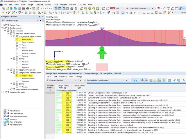
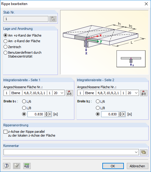
It can happen that all design checks are fulfilled for a particular member or set of members, but a "Not Covered Reinforcement" result is still output. See also Image 01 and Image 02.
The reason for this is that the distribution of the "Provided Reinforcement" on the upper and lower positions is generated from the rebar arrangement within the cross-section.
The rebars above the center of gravity are assigned to the "upper position" and the rebars below the center of gravity are assigned to the "lower position". This means that the distribution of the "Provided Reinforcement" does not consider the actual distribution of the zero line within the cross-section, and checks which rebar is actually in the tension zone.
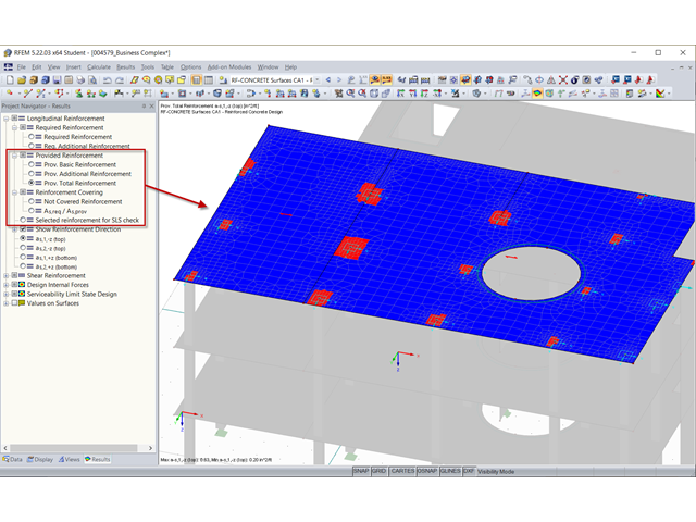
However, the actual distribution of the zero line within the cross-section is checked during the design. Thus, the rebars that have been geometrically assigned to the "lower reinforcement" (the provided reinforcement distribution) can be mathematically assigned to the tension reinforcement. This can be seen in Image 03. The rebars marked in red have been assigned geometrically to the lower reinforcement. However, the stress distribution within the cross-section shows that they are also subjected to tension and apply to the design checks accordingly. In the design, all members (marked in red and green in Image 03) are applied. Therefore, all the design checks are fulfilled at this location, although the distribution of the "Not Covered Reinforcement" suggests otherwise.
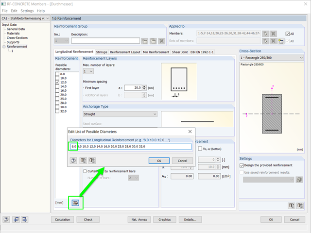
The list of possible diameters can be extended or modified in the add-on modules CONCRETE, RF‑CONCRETE Members, and RF‑/CONCRETE Columns using the "Edit List of Possible Diameters" button.
No, this is not possible in RF‑CONCRETE Surfaces (in the current state of development).
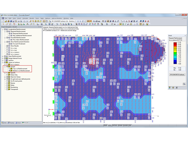
If you have activated a basic reinforcement and/or the serviceability limit state design in RF‑CONCRETE Surfaces, there are several options available in the Results navigator for the graphical display of the "provided reinforcement".
However, no rendering of rebars or mesh reinforcement is generated in this case. It is rather a color representation of the result values in [cm²/m] for the longitudinal reinforcement or in [cm²/m²] for the shear reinforcement.
You can display the reinforcement direction in two ways:
1. Activate the "Show Reinforcement Direction" option in the Results navigator. In addition, you can activate the "For Each FE Element" option. It is particularly interesting if the alignment of the FE axes is curved or arranged radially.
2. When using the "Values on Surfaces" and the "Groups" option, the result values are shown in the direction in which the rebars are placed.
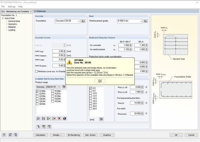
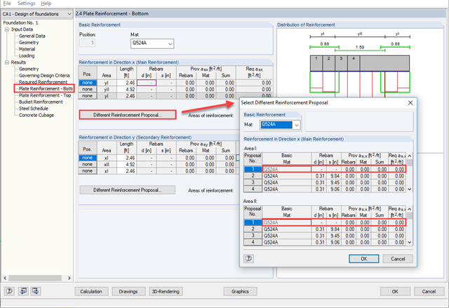
In Window 1.3 Materials, it is not possible to deactivate all reinforcing bars. At least one diameter must be selected here. However, you can determine the bending reinforcement required for the foundation plate with this specification in one of the first calculation steps. In result window 2.3 Required Reinforcement, you can then see which bending reinforcement is to be provided for the foundation plate. Afterwards, you can specify a user-defined reinforcement in Window 2.4 Plate Reinforcement - Bottom. To do this, click the Different Reinforcement Proposal... button. A new dialog box appears where you can specify that only mat reinforcement should be applied (no rebars). Click [OK] to confirm the change in this dialog box. If you click in the module navigator after this change, you will receive a message indicating that the calculation must be performed again due to the change in the reinforcement. Confirm this by clicking [Yes]. Thus, the calculation will be performed again. After the recalculation, you can open Window 2.7 Steel Schedule. Here you can see that only reinforcing mats have been used.